At the end of 2017, the Fitel team started to deploy fiber optics. Fibre was installed in the main urban locations of the city of Lloret de Mar. The topology that the technical management team decided to use is FTTH and FTTB, with GPON technology. Currently, the network is designed to connect over 10,000 fiber ONT devices. Services that are provided to end-users include VOIP and Mobile connections. The company connects companies and residential customers that pay on a monthly basis (recurring) and has a number of customers who come to Lloret de Mar for a vacation and pay for services in a prepaid mode.
This case study will give you a brief overview of how the Splynx ISP billing system enabled The Fitel Network’s optimization, redesigning the core network to allow 10G throughput, registering AS, IPv4, and IPv6 address spaces, and deployment of BGP services to their customers.

Let us describe how this project started and its progress
In the middle of 2018, Fitel Networks requested our team to install and deploy Splynx billing software. During installation and implementation, we noticed that the main MikroTik CCR router was having some strange issues. PPPoE users were continuously disconnecting, packets were lost and router behavior was unstable. Fitel’s technical officer Paul Gerhardt asked us to investigate if the problem was caused by the Splynx software, but we knew that Splynx can reconnect PPPoE sessions only in one case – when an administrator sends COA or the ‘kill session’ command. Our engineers were aware of this and started to analyze the network design.
The company had Huawei MA5608 OLT equipment installed, which worked in bridge mode, terminating all PPPoE connections on a MikroTik CCR1036 router. This router was performing the role of PPPoE concentrator and NAT server. When the network had only wireless customers at around 800 Mbps, the router was performing well, but when the first few hundred GPON customers were connected, the router’s traffic reached 1.4 Gbps and the issues started.
The main issue was that once a day at around 4 pm, several customers reconnected their PPPoE sessions, which caused the CPU activity to jump from 30% to 100%, and, as a result, the router stopped responding to new PPPoE requests. Also, it started to disconnect dozens of already-connected PPPoE customers.
A short investigation from our team showed that NAT connections tracking together with a large number of PPPoE connections and hence high traffic gives this issue. We offered Fitel Networks our service of network redesign and optimization.
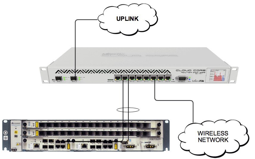
The initial topology looked as in the picture provided below:

- Wireless network. All users connect through the network on L2 bridges up to a CCR router. Customers have UBNT or MikroTik CPE equipment that works as a transparent bridge. Each customer has a TP-Link or MikroTik router installed on the premises which establishes a PPPoE connection and also connects end users’ devices to their home Wi-Fi networks.
- Fibre network. A Huawei MA5608 router is connected to a MikroTik CCR router with two Gigabit interfaces. Interfaces are bonded using LACP. The company planned to migrate to 10G interfaces and was waiting for the module car
- MikroTik CCR1036. The router was connected via a 10G port to the uplink with PPPoE and NAT server running on it.
Splynx team has experience with designing ISP networks for over 10G loads. We have built and optimized several wireless and fiber networks and it is one of the services that a customer can get from us when deploying Splynx ISP software. The main point of the whole optimization was to move out the load from one main MikroTik router and share it between different equipment. There was also another reason – to change the MikroTik router that is CPU routing-based to some hardware accelerated router, for example, Juniper, Alcatel, or Cisco.
Fitel Network’s IT team has MikroTik knowledge and, as such, changing the platform was very painless. We decided to take more than one MikroTik router, add switches to have L2 redundant topology, and share the load between different equipment.
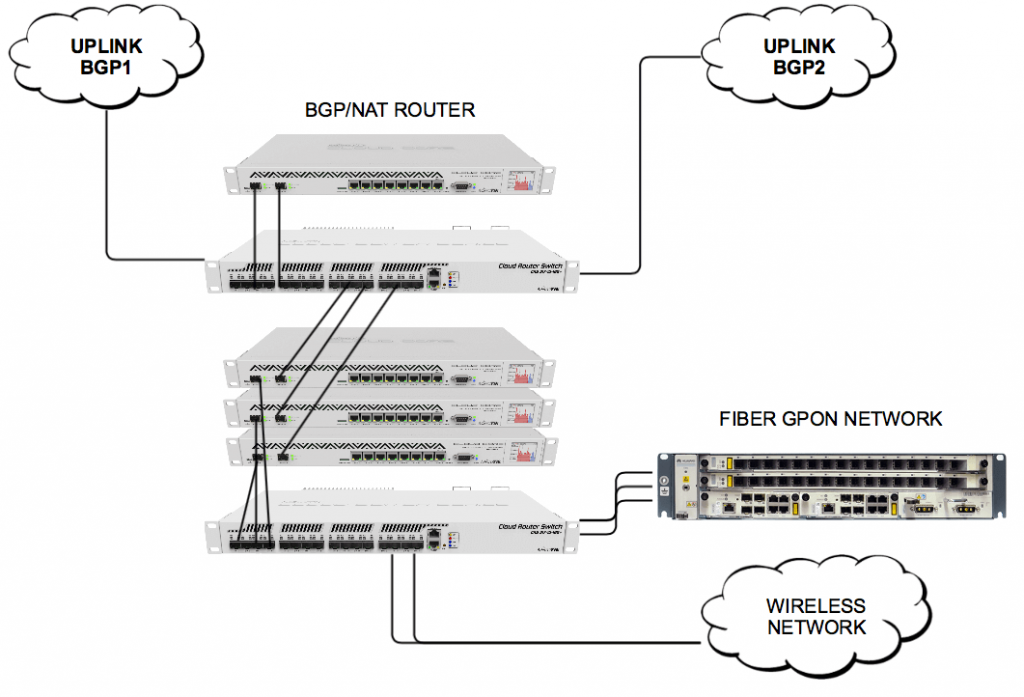
The result of the redesign and optimization is presented in the picture below:

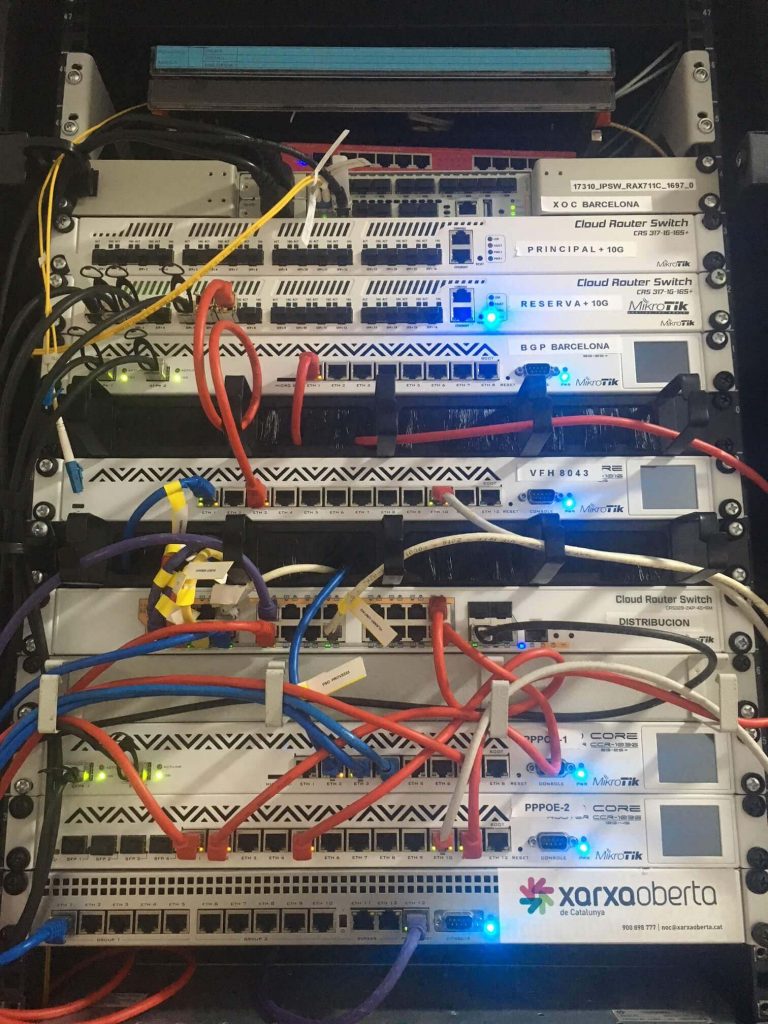
Logical topology created in visualization software:

Equipment that was installed
A MikroTik CCR1036 router acts as the BGP and NAT router.
MikroTik CRS317 16 ports SFP+ – core switch, is connected to uplink 10G ports, a BGP router, and all three PPPoE routers are also connected via 10G ports. Please note that the same switch is installed just close to the first one. The second switch acts as a cold backup. This means it has exactly the same configuration as the core switch and the same amount of ports, ready to swap in case of failure of the first switch.
3x MikroTik CCR1036 routers that work as PPPoE servers where fiber and wireless clients are connected.
MikroTik CRS328 24 ports + 4 SFP ports, which acts as a distribution switch. To this switch are connected GPON OLT and links coming from wireless towers. Also, PPPoE router downlinks are plugged-in to this switch.
A BGP router announces public prefixes to the Internet and routes traffic between two Internet providers. Uplinks are 10GB lines. Each PPPoE router has its own private 172.16.x.x network from which we assign IP addresses to private and prepaid customers. It means that on the BGP router there are three installed static routes to these networks – each network to a proper PPPoE router.
PPPoE servers are connected to the same switch on the same VLANs, which means that users from fiber and wireless networks can connect to one of three PPPoE servers at the same time. The advantage of this approach is scalability and failover. If one router fails, customers can automatically reconnect to the two remaining PPPoE routers.
PPPoE routers are linked with the Splynx Radius server. When a customer connects to router 1, he gets the IP from the pool, which is dedicated for this certain router.
Another story is with public IP addresses. In this case, customers have a static IP address, which means that physically they can connect to any PPPoE server.
To know where the BGP router should send traffic, we have activated OSPF on three links – between each PPPoE concentrator and the BGP router. PPPoE customers’ IPs are redistributed to OSPF as connected routes as soon as they connect to the Internet. It is important to set the routing filters correctly – allowing only public IPs in a routing table with /32 routes, and all private IPs are not redistributed to the OSPF.
Your software has made our daily tasks more easy and visible. We really do have control over our processes (invoicing, networking, messaging, etc). The CRM system is great to assign tasks to our field engineers, who can manage their own calendars.


